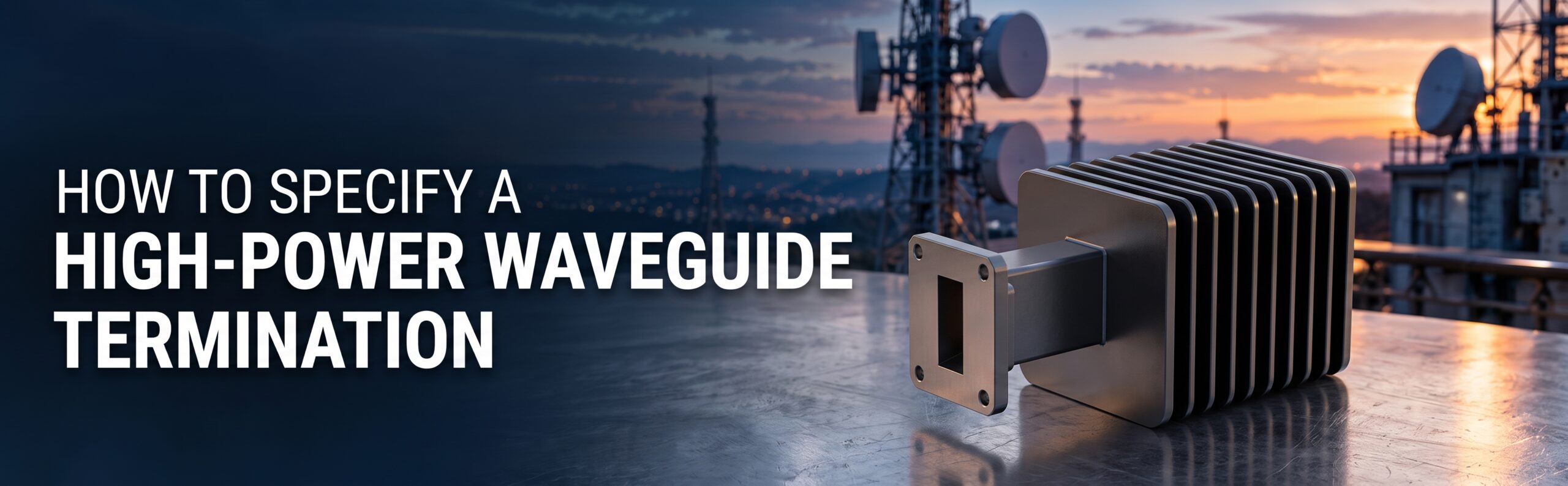
A waveguide termination absorbs microwave energy at the end of a signal path. It may be used during testing or as part of a system where energy needs to be directed into a load.
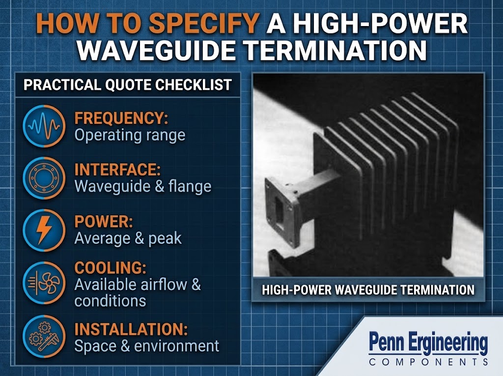
Selecting one involves more than matching the flange and choosing a power rating. The operating frequency, power over time, cooling conditions, and installation all affect whether a termination is suitable.
You do not need a lengthy specification to begin the discussion. A clear description of the operating conditions is a useful starting point.
Confirm the frequency range
Start with the lowest and highest frequencies the termination needs to handle.
The waveguide size helps narrow the options, but it does not establish the operating range of every termination made with that interface. Confirm the frequency range for the specific product or configuration.
For a replacement, include the existing part number and drawing if available. Also note whether the operating conditions have changed since the original part was selected.
Separate average power from peak power
“High power” can describe different operating conditions. A system transmitting continuously places different demands on a termination than one transmitting short pulses.
Two figures are especially useful:
Average power describes the power absorbed over time. It is important when reviewing heat buildup and cooling needs.
Peak power describes the highest power during a pulse or other brief operating event. A product that meets an average-power requirement may still need separate review for peak power.
Provide both figures when they apply. If the system is pulsed, also include the pulse duration and repetition rate, or the duty cycle if known.
If those values are still being developed, identify them as preliminary.
Explain how the termination will be cooled
Absorbed energy becomes heat, and that heat must be managed.
A termination’s rating depends on its specified operating conditions. Available airflow, surrounding temperature, mounting, and any required cooling supply can affect its suitability.
Describe the installation as it will actually operate. For example, a unit installed inside a crowded enclosure may face different conditions from one used on an open test bench.
If a product requires a particular cooling arrangement, confirm that the installation can provide it. Ask the supplier which cooling options are available for the application.
Identify the connection and installation limits
Provide the waveguide size and full flange designation, including the mating arrangement where possible.
Then explain any physical limits:
- Space available for the termination.
- Mounting position and support requirements.
- Access needed for installation or maintenance.
- Pressure or sealing requirements.
- Temperature, vibration, or other environmental conditions.
A drawing or photograph of the installation can help communicate these details, especially when replacing a part in an existing system.
Include any reflected-power requirement
A termination is intended to absorb energy, but some energy can reflect back toward the source.
The acceptable level of reflection may be specified as VSWR or return loss. If the system documentation includes either requirement, pass it along with the frequency range.
There is no need to choose a tighter requirement simply because it sounds better. Use the system’s actual needs and confirm that the proposed termination meets them under the stated operating conditions.
Start with the application
A suitable termination needs to match the way the system operates, not just its nominal power level.
Penn Engineering’s high-power termination page is a starting point for reviewing the product. When requesting a quote, share the frequency range, power conditions, interface, and installation details so the proposed configuration can be checked against your requirements.
To discuss your defense systems and waveguide requirements