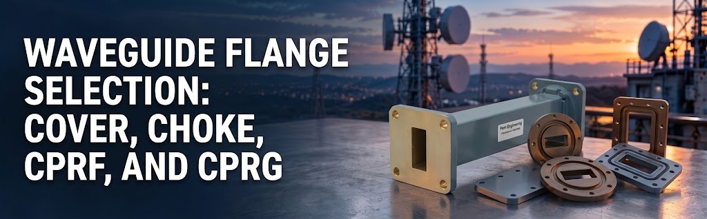
A waveguide flange connects one section of an RF or microwave waveguide system to another. Choosing the right waveguide flange ensures a precise mechanical fit while supporting the strict electrical and environmental sealing requirements of your connection.
The challenge is that similar-looking waveguide components may have entirely different functions. A matching bolt pattern is only part of the picture.
Understanding a few common flange designations can help you review a drawing, identify an existing RF connection, or prepare a more complete and accurate quote request.
How to Identify the Right Flange: Begin with the Mating Connection
For a replacement or an addition to an existing microwave or RF system, always start by evaluating the flange on the part you need to connect to.
Look for a specific flange designation on the drawing, equipment documentation, or part record. It is also critical to confirm the precise waveguide size.
While a photograph can help explain the arrangement, it may not show the dimensions, internal grooves, or other micro-details needed to establish true compatibility. If the designation is unknown, a dimensioned drawing and clear views of the flange face are the best next steps.
Pro Tip: Avoid selecting a waveguide flange based on appearance alone.
What is a Cover Waveguide Flange?
A cover flange generally features a flat mating face around the waveguide opening.
It is a highly common connection style, but the term “cover flange” does not identify every detail needed to order the correct part. The waveguide size, flange standard, hole pattern, material, and specific mating arrangement still need to be established.
Where environmental sealing is required, review the complete connection rather than assuming that a flat face will provide the necessary seal by itself.
What is a Choke Flange in RF Design?
A choke flange includes a specialized groove designed to help control the electrical behavior and minimize RF leakage at the joint.
That groove is a critical part of the connection’s RF design. It should never be treated as interchangeable with a standard sealing groove simply because both are recessed features.
Choke arrangements are engineered to work with a particular mating flange. The correct pairing depends on the applicable design or standard, so you must confirm both sides of the joint before ordering.
CPRF vs. CPRG: Pressurized Rectangular Waveguide Flanges
CPR is a flange designation used for rectangular waveguide connections designed specifically to support pressurization.
Within this flange family:
- CPRF identifies a flat-face flange version.
- CPRG identifies a grooved-face flange version.
The CPRG groove accommodates the specified sealing arrangement. However, the full flange designation, including its physical size, is still required to properly identify the connection.
Whether a joint requires a gasket—and exactly which gasket it requires—depends heavily on the mating arrangement and environmental operating conditions. Always confirm those details together.
Waveguide Flange Selection Checklist: Beyond the Name
Once you have identified the general flange type, review the rest of the connection criteria to ensure optimal performance.
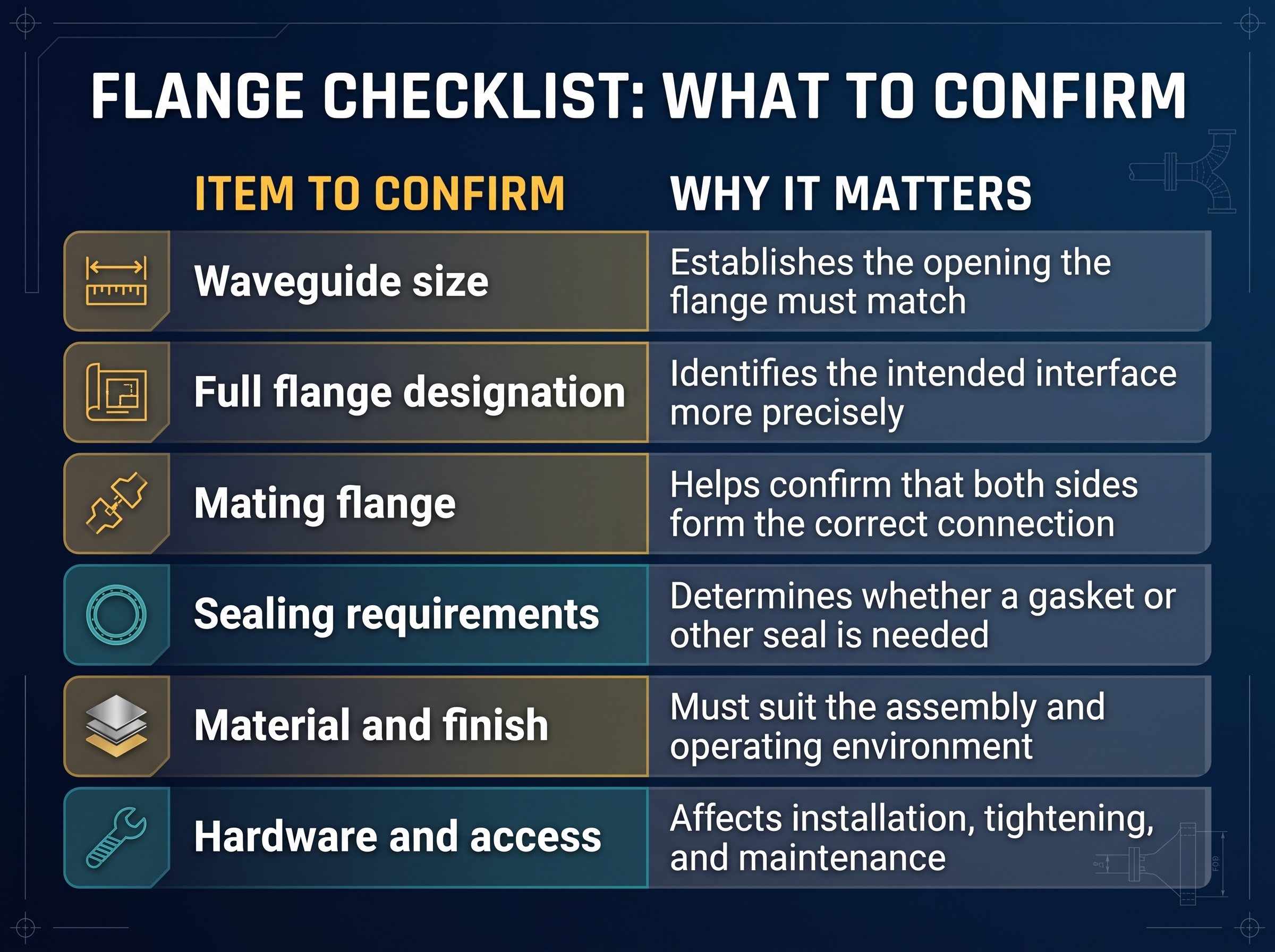
For communications or defense equipment operating under pressure or in demanding environmental conditions, explicitly include those requirements in your specification. Do not assume that a flange designation alone establishes the mechanical or RF performance of the finished joint.
What to Include in a Waveguide Flange Quote Request
A useful and efficient quote request includes the waveguide size, full flange designation, material type, quantity, and drawing revision.
Also, identify the mating flange and any specific gasket, hardware, pressure, or environmental requirements. For a custom waveguide flange, provide a dimensioned drawing and clearly note any features that differ from the standard interface.
Penn Engineering’s waveguide flange catalog page lists our standard flange families and related technical information. If you are unsure which RF connection you have, share the documentation available and ask our team which dimensions or details are needed to confirm it.
To discuss your defense systems and waveguide requirements