Description
Miter Bends E and H Plane with Flanges
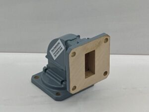
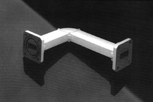
PENN ENGINEERING offers a standard line of mitered waveguide bends for us in a waveguide system. Use these standard lengths to design your system, or give us your dimensions for a custom e-bend/h-bend combination and we will build them to your specifications.
Typical VSWR for standard mitered bends is 1.05:1 over the full frequency range.
Brass bends are Silver Plated per QQ-S-365D Class A, Aluminum Bends are Chem-filmed per MIL-C-5541E, and both are finished with PENN ENGINEERING’S Metallic Blue Paint.


Additional information
| Component Type | "E" Bend, "H" Bend |
|---|---|
| Waveguide Size | WR 284 (S-Band), WR 229, WR 187, WR 159, WR 137 (C-Band), WR 112, WR 102, WR 90 (X-Band), WR 75, WR 62 (P-Band), WR 51, WR 42 (K-Band), WR 28 (R-Band) |
| Leg 1 Flange | Cover, Choke, CMR, CPRG, CPRF |
| Leg 2 Flange | Cover, Choke, CMR, CPRG, CPRF |
| Alloy | Aluminum, Bronze/Brass, Copper, Silver, Stainless Steel |
| Plating | Chem-Film, Gold(Immersion), Nickel, 8P Irridite, Silver(Immersion), Tin, None |
| Paint | Blue, Grey, Hammertone-Silver, Black, White, Z306 (Black), Z307 (Black), None |
Specifications
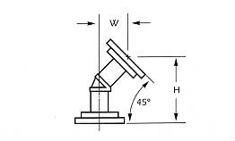
| Model # | 45 Degree “E” Plane | Model # | 45 Degree “H” Plane | Waveguide EIA | Frequency Range (GHz) | ||
| W | H | W | H | ||||
| 2656 | 1.875 | 4.5 | 2756 | 2.093 | 5.031 | WR 284 | 2.60-3.95 |
| 2654 | 1.062 | 2.656 | 2754 | 1.312 | 3.062 | WR 229 | 3.30-4.90 |
| 2652 | 1.437 | 3.468 | 2752 | 1.531 | 3.812 | WR 187 | 3.95-5.85 |
| 2650 | 1.25 | 3.0 | 2750 | 1.218 | 2.906 | WR 159 | 4.90-7.05 |
| 2648 | 1.125 | 2.687 | 2748 | 1.218 | 2.937 | WR 137 | 5.85-8.20 |
| 2646 | 1.093 | 2.625 | 2746 | 1.187 | 2.875 | WR 112 | 7.05-10.0 |
| 2644 | 1.093 | 2.625 | 2744 | 1.187 | 2.875 | WR 102 | 7.00-11.0 |
| 2642 | .968 | 2.312 | 2742 | 1.031 | 2.5 | WR 90 | 8.20-12.4 |
| 2640 | .687 | 1.687 | 2740 | 0.687 | 1.687 | WR 75 | 10.0-15.0 |
| 2638 | .687 | 1.687 | 2738 | 0.687 | 1.687 | WR 62 | 12.4-18.0 |
| 2636 | .687 | 1.687 | 2736 | 0.687 | 1.687 | WR 51 | 15.0-22.0 |
| 2634 | .687 | 1.687 | 2734 | 0.687 | 1.687 | WR 42 | 18.0-26.5 |
| 2630 | .687 | 1.687 | 2730 | 0.687 | 1.687 | WR 28 | 26.5-40.0 |
Difference Between E and H Bends
How to Tell the Difference Between E and H Bends
 The terms “E” and “H” plane refers to the electrical and magnetic planes of rectangular waveguide. The electrical plane or E-plane is the narrow plane of the waveguide and the magnetic plane or H-plane of the waveguide is the wide plane.
A simple way to remember this is that an E-bend is the “easy” way to bend waveguide and an H-bend is the “hard” way to bend waveguide.
Related products
-

90 Degree Miter Bends
Price on Quote Request Quote This product has multiple variants. The options may be chosen on the product page

